Hydroelectric Concrete Restoration
Project Type

Project Description
Concrete gravity Dam
Underwater Concrete Placement (Water Power Project – applicable to any industry with concrete water retaining structure)
 A concrete gravity dam with an earth core and rock/soil foundation was completed in 1944. The dam is 8,422 feet long, 206 feet high with a 130 foot head. Maximum storage is 6,129,000 acre-feet and the purpose is navigation, flood control, power production, and recreation. The downstream side is a radial gate controlled spillway 960’ wide with a maximum discharge of 1,050,000 cfs.
Eddies created by a change in the gate operation sequence deposited gravel on the downstream concrete apron. A resulting eddy between the downstream flow blocks and the apron toe caused a ball mill type action that eroded the concrete apron.
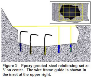
The repair designed called for the placement of number six rebar in each erosion area as shown in Figure 9. Twelve-inch deep holes were to be drilled on three-foot centers and the reinforcing steel was epoxy grouted in place. Since underwater visibility was limited to a few inches, the Engineer directed divers to construct a wire template to aid in aligning each hole. Measurements were then taken so that each piece of reinforcing could be sized to leave three inches of cover at the repair surface. Concrete would be placed by bucket and designed so that it could be dropped through up to seven feet of water.
The success of the repair depended largely on the concrete mix design. Because the diving contractor was experienced in placing concrete underwater, he was able to make helpful recommendations to the Engineers designing the concrete. The mix would need excellent cohesive strength in the submerged application and had to be resistant to washout of cement. Its ability to self-compact and self-level and its workability at low water to cement ratios would also be important. Because of the poor visibility, the divers would need as much working time as possible to place the concrete.
 Divers used oxy-arc cutting torches to remove damaged 1-1/4” steel reinforcing. Loose debris was removed from the repair areas using a combination of low pressure water jetting and hand dredging. Damaged concrete was then removed by 5,000 psi high-pressure water. Before placing concrete, divers conducted a video inspection so that the Engineer could verify the preparation of the repair areas.
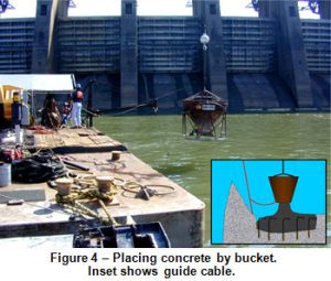
A cable was anchored to the apron adjacent to the repair area. The concrete bucket was tethered to the cable at the surface and then lowered to the bottom as shown in Figure 10. Once the bucket reached the apron, the diver could safely move in and adjust its position. Buckets were positioned within twelve to eighteen inches of the steel reinforcing and then opened to release the concrete. Only minimal hand toweling was required to provide the desired surface. A final video inspection was performed to approve each repair.